

_副本")
_副本")
_副本")
Introduction to CCC MCP-1004
Product Description
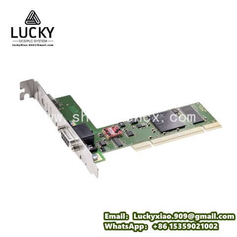
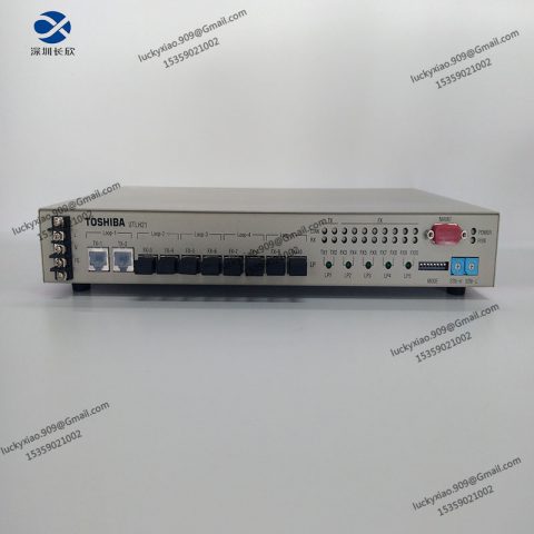
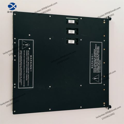
The CCC MCP-1004 is a compact, high-performance motion control module designed for industrial automation systems, primarily used in precision manufacturing, robotics, and material handling applications. As a core component of CCC’s motion control product line, it integrates multi-axis control, real-time trajectory planning, and synchronization capabilities to drive servo motors and stepper motors with high accuracy.
This module features a modular design, supporting seamless integration with PLCs, HMI systems, and industrial networks. Its robust industrial-grade construction ensures reliable operation in harsh environments with temperature fluctuations, vibration, and electromagnetic interference. Equipped with advanced control algorithms (such as PID with feedforward), the MCP-1004 delivers precise speed, position, and torque control, making it ideal for applications requiring tight motion synchronization, such as CNC machines, packaging lines, and automated assembly stations.
Technical Specifications
- Axis Configuration: Supports 4 independent axes, compatible with servo motors (AC/DC) and stepper motors.
- Control Modes: Position control (pulse/direction, CW/CCW), speed control (analog voltage/PWM), torque control (current command).
- Positioning Accuracy: ≤ ±0.01 mm (when paired with 1000-line encoders); repeatability: ≤ ±0.005 mm.
- Maximum Pulse Output: 2 MHz per axis (differential line driver output).
- Feedback Support: Incremental encoders (A/B/Z), absolute encoders (SSI, BISS-C), analog feedback (potentiometers).
- I/O Signals: 16 digital inputs (24V DC, PNP/NPN configurable) for limit switches, home sensors, etc.; 8 digital outputs (24V DC, 2A max) for relays or actuators.
- Communication Interfaces: EtherCAT (100 Mbps, cycle time ≥ 100 µs), RS485 (Modbus RTU), USB (configuration/debugging).
- Power Requirements: 24V DC ±10% input; power consumption: ≤ 15W (excluding motor power).
- Environmental Ratings: Operating temperature: -10°C to +60°C; storage temperature: -25°C to +70°C; relative humidity: 10% to 90% (non-condensing); vibration resistance: 10-500 Hz, 10 g (IEC 60068-2-6).
- Mechanical Dimensions: 120 mm × 80 mm × 30 mm (L × W × H); mounting: DIN rail (35mm) or panel-mount with screws.
Operating Instructions
- Installation:
-
- Mount the module on a 35mm DIN rail or secure it to a panel using M3 screws (torque: 0.5-0.8 N·m). Ensure a minimum 20mm clearance around the module for ventilation.
-
- Avoid direct exposure to dust, moisture, or strong magnetic fields (e.g., transformers, large motors).
- Wiring:
-
- Power: Connect 24V DC to the “V+”/”0V” terminals; use 1.5 mm² copper wire and secure with terminal blocks (torque: 0.6 N·m).
-
- Motor Connections: Connect servo/stepper motor drivers to the axis output terminals (pulse, direction, enable signals). Use twisted-pair cables for differential signals.
-
- Feedback: Wire encoders to the dedicated feedback ports, ensuring correct polarity for A/B phases.
-
- I/O Signals: Connect limit switches, sensors, and actuators to the digital I/O terminals; configure PNP/NPN via DIP switches.
-
- Communication: Link EtherCAT to the industrial network using shielded twisted-pair cable (CAT5e or higher); ground the shield at one end.
- Configuration:
-
- Use CCC Motion Studio software (via USB or EtherCAT) to configure axis parameters: motor type, encoder resolution, acceleration/deceleration rates, and PID gains.
-
- Define motion profiles (point-to-point, linear interpolation, circular interpolation) and I/O logic (e.g., trigger motion on sensor input).
-
- Save configurations to the module’s non-volatile memory; test with a dry run to verify positioning and synchronization.
- Operation & Maintenance:
-
- Power on the module; check the status LED (green = normal, red = fault). Use software to monitor axis status, error codes, and feedback data.
-
- Perform routine checks monthly: inspect wiring for looseness, clean dust from vents, and verify encoder signal integrity.
-
- Calibrate PID parameters annually or after motor/driver replacement to optimize dynamic performance.
System Integration
The CCC MCP-1004 functions as a critical motion control node within industrial automation systems, integrating with multiple layers:
- Sensor Layer: Connects to limit switches, home sensors, and encoders to provide real-time position feedback and safety interlocks.
- Control Layer: Receives motion commands from a PLC or HMI via EtherCAT, executing preprogrammed trajectories (e.g., linear moves, jogging) with microsecond-level synchronization between axes.
- Actuator Layer: Drives servo/stepper motor drivers, translating electrical commands into precise mechanical motion (e.g., CNC axis positioning, robotic arm movement).
- Network Layer: Communicates with supervisory systems (SCADA/MES) via Modbus RTU, enabling remote monitoring of motion status, error logs, and performance metrics.
Typical Application: In a 3D printer assembly line, the MCP-1004 controls 4 axes (X, Y, Z, and extruder), synchronizing their movements to deposit material with sub-millimeter accuracy. EtherCAT ensures real-time coordination, while limit switches connected to digital inputs prevent overtravel.
Related Series Models
- CCC MCP-1002: 2-axis compact version, identical features to MCP-1004 but with reduced axes; ideal for simple pick-and-place machines.
- CCC MCP-1008: 8-axis high-density module, supporting coordinated motion for complex systems (e.g., multi-axis CNC routers).
- CCC MCP-1004-EX: Explosion-proof variant (ATEX II 3G), certified for hazardous areas (e.g., chemical processing machinery).
- CCC MCP-1004-LV: Low-voltage version (12V DC input) for battery-powered or mobile applications (e.g., AGVs).
- CCC MCP-1004-PRO: Advanced model with built-in motion planning (spline interpolation) and machine vision integration via GigE Vision.
- CCC MCP-IO-16: Expansion I/O module (16 inputs/16 outputs) for MCP-1004, extending sensor/actuator connectivity in large systems.

-480x480.jpg)
There are no reviews yet.