


Introduction to DEIF RMC-131D/2
Product Description
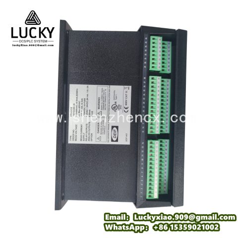
The DEIF RMC-131D/2 is a versatile remote monitoring and control unit designed for decentralized energy systems, generator sets, and industrial power networks. As a key component in DEIF’s range of energy management solutions, this unit specializes in enabling remote supervision, data logging, and control of two connected devices (typically generators or grid connections), making it ideal for applications such as off-grid renewable energy systems, distributed generation networks, and remote infrastructure with limited on-site personnel.
The “RMC-131D/2” designation reflects its core functionality: “RMC” (Remote Monitoring and Control) highlights its focus on remote operations, “131D” indicates a mid-range feature set with digital I/O capabilities, and “2” specifies support for two monitored assets. Unlike basic monitoring devices, the RMC-131D/2 combines real-time data acquisition with programmable control logic, allowing users to automate responses to system events (e.g., starting a backup generator when grid power fails) without manual intervention. Its robust design ensures reliable operation in harsh environments, while flexible communication options enable seamless integration with central management systems.
Technical Parameters
- Power Supply: 24V DC (18-32V DC)
- Power Consumption: ≤8W (standby); ≤12W (active with all outputs)
- Input Channels:
-
- Analog: 8 inputs (4-20mA or 0-10V) for sensors (e.g., temperature, pressure, level)
-
- Digital: 12 inputs (dry contact or 24V DC) for status signals (e.g., breaker position, alarm contacts)
- Output Channels:
-
- Digital: 8 relay outputs (SPDT, 5A/250V AC) for control (e.g., start/stop, breaker control)
-
- Analog: 2 outputs (4-20mA) for proportional control (e.g., valve positioning)
- Communication Interfaces:
-
- Primary: RS485 (Modbus RTU)
-
- Secondary: Ethernet (Modbus TCP/IP, optional)
-
- Wireless: 4G/LTE (optional, for remote sites)
- Data Logging: Internal memory for 100,000 data points; configurable logging intervals (1s to 1h)
- Operating Temperature: -30°C to +70°C (-22°F to +158°F)
- Storage Temperature: -40°C to +85°C (-40°F to +185°F)
- Relative Humidity: 5-95% RH (non-condensing)
- Vibration Resistance: 10-500Hz, 10g peak (IEC 60068-2-6)
- Protection Rating: IP42 (front panel); IP20 (terminal block)
- Dimensions: 144mm × 144mm × 130mm (W × H × D)
- Weight: Approximately 1.3kg
- Certifications: IEC 61131-2, CE, UL 508, DNV GL
Usage Methods
- Installation:
-
- Mount the unit on a DIN rail or panel in a control cabinet, ensuring vertical orientation for optimal heat dissipation.
-
- Position in a location with minimal exposure to direct sunlight, moisture, and electromagnetic interference from high-voltage equipment.
-
- Allow 30mm clearance around the unit for wiring access and ventilation, particularly in enclosed cabinets.
- Wiring and Connection:
-
- Connect analog sensors (e.g., fuel level transmitters, temperature probes) to the analog input terminals, ensuring correct scaling (4-20mA or 0-10V).
-
- Wire digital inputs to status contacts (e.g., generator running, grid available) using twisted-pair cable.
-
- Connect relay outputs to control devices (e.g., generator start relays, breaker coils), ensuring load currents do not exceed 5A.
-
- Establish communication links: hardwire RS485/Ethernet to the central system, or install the optional 4G module with an external antenna for wireless connectivity.
-
- Power the unit with a 24V DC supply, using a fused circuit (1A) to protect against overcurrent.
- Configuration:
-
- Use DEIF’s RMC Configurator software to map inputs/outputs to monitored parameters (e.g., Analog Input 1 = Fuel Level).
-
- Program control logic via ladder diagram or function block diagrams (IEC 61131-3 compliant), defining rules such as “If Grid Voltage < 200V → Start Generator 1”.
-
- Set up data logging parameters, specifying which variables to record (e.g., generator load, battery voltage) and logging frequency.
-
- Configure communication settings (IP address for Ethernet, APN for 4G) to enable remote access via SCADA or DEIF’s Energy Manager platform.
- Operation and Maintenance:
-
- Monitor system status via the front-panel LCD or remote software, viewing real-time data and alarm logs.
-
- Retrieve logged data periodically via USB or network download for performance analysis and compliance reporting.
-
- Test control logic monthly by simulating inputs (e.g., triggering a “grid loss” signal) to verify automated responses.
-
- Inspect wiring connections quarterly, tightening terminals to prevent vibration-induced loosening.
-
- Update firmware annually via Ethernet or USB to access new features and security enhancements.
System Introduction
The DEIF RMC-131D/2 serves as a critical bridge between field devices and central management systems, integrating four key functions:
- Data Acquisition Layer: Collects analog and digital data from connected assets, converting raw signals into meaningful parameters (e.g., “Fuel Level = 75%”).
- Processing Layer: Executes user-defined control logic to automate responses, such as starting a backup generator when renewable energy output drops below demand.
- Storage Layer: Logs historical data for trend analysis, enabling predictive maintenance (e.g., scheduling generator servicing based on run hours).
- Communication Layer: Transmits real-time and historical data to central systems, while receiving remote commands (e.g., manual generator start) from operators.
In a solar-diesel hybrid system at a remote village, the RMC-131D/2 monitors the solar inverter and a diesel generator. It logs solar output, battery state of charge, and generator run hours. When battery voltage drops below 45%, the unit automatically starts the generator to prevent blackouts. Operators in a central office access real-time data via 4G, adjusting parameters (e.g., generator start threshold) remotely to optimize fuel usage.
Related Models in the Series
- DEIF RMC-131D/4: Supports four monitored assets, suitable for larger systems with multiple generators or renewable energy sources.
- DEIF RMC-131D/2-EX: Explosion-proof version (ATEX/IECEx Zone 2) for hazardous environments like oil and gas facilities.
- DEIF RMC-131D/2-W: Wireless-only model with integrated LoRa for low-power, long-range communication in remote areas.
- DEIF RMC-132D/2: Advanced variant with expanded analog I/O (16 inputs, 4 outputs) and enhanced data logging (1 million points).
- DEIF RMC-131D/2-LT: Low-temperature optimized unit (-40°C to +70°C) for arctic or high-altitude applications.
- DEIF RMC-101D/2: Entry-level model with reduced I/O (4 analog inputs, 4 relays) for cost-sensitive small-scale systems.

-480x480.jpg)
There are no reviews yet.