


Introduction to EMEROSN A6500-CC
Product Description
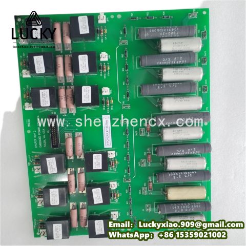
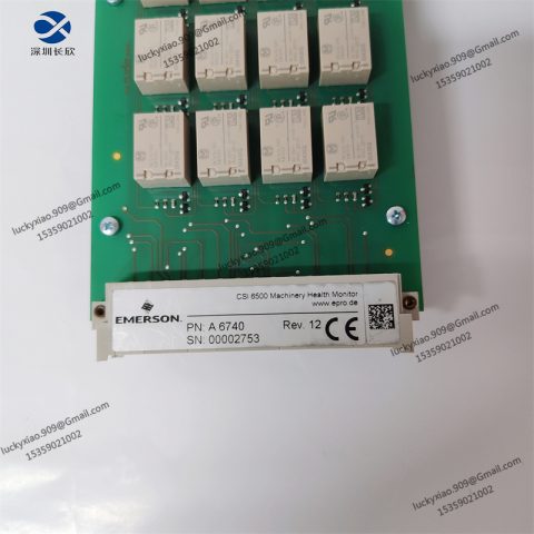
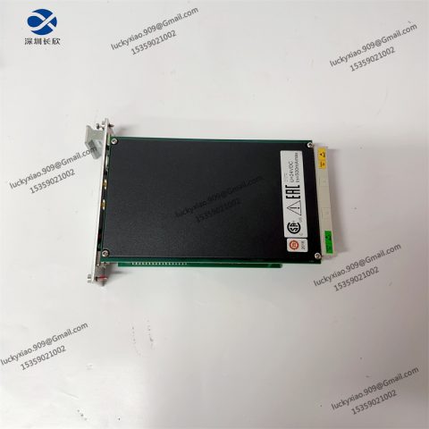
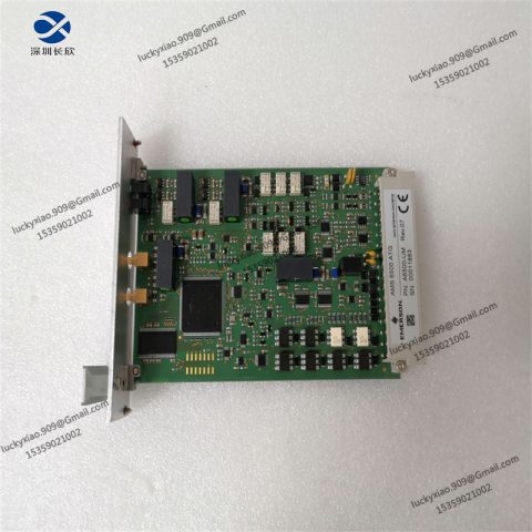
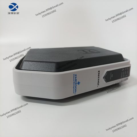
The EMEROSN A6500-CC is a rugged, mid-range industrial control unit designed for distributed process control and machine automation in demanding industrial environments. Targeted at industries such as petrochemical processing, water/wastewater treatment, food and beverage manufacturing, and discrete manufacturing (e.g., automotive component assembly), this control unit excels at integrating sensor data, executing logic control, and communicating with upstream systems—making it ideal for applications requiring reliable, real-time monitoring and control of medium-scale processes.
The model designation “A6500-CC” encodes key functional attributes (inferred from industrial control product standards): “A6500” denotes the product series (mid-tier performance, expanded I/O capacity), and “CC” signifies “Central Control” with integrated communication capabilities (supporting multi-protocol fieldbus and network connectivity). Unlike basic PLCs, the A6500-CC combines modular I/O expansion, advanced process control algorithms (e.g., PID, cascade control), and built-in cybersecurity features—enabling it to handle complex tasks such as batch processing, temperature/pressure regulation, and sequence control. Its robust mechanical design (reinforced housing, wide temperature tolerance) ensures operation in harsh conditions, including dusty environments, temperature fluctuations, and moderate vibration—common in process industries.
Typical use cases include:
- Regulation of temperature and pressure in petrochemical refining units.
- Sequential control of filling and capping processes in beverage bottling lines.
- Monitoring and control of pump stations in water treatment plants.
- Integration of IoT sensor networks for predictive maintenance in manufacturing cells.
Technical Parameters
- Processor: 32-bit industrial-grade CPU (1.0 GHz, dual-core) with floating-point unit (FPU) for complex control calculations.
- Memory:
-
- Program Memory: 8 MB flash (expandable to 16 MB via industrial SD card).
-
- Data Memory: 1 MB RAM (with battery backup for 72 hours of data retention during power loss).
- Operating System: Proprietary Real-Time Operating System (RTOS) with deterministic task execution (≤1ms loop latency for control tasks).
- I/O Capabilities:
-
- Built-in I/O:
-
-
- Digital Inputs: 16 channels (24V DC, PNP/NPN configurable, response time ≤10µs).
-
-
-
- Digital Outputs: 8 channels (24V DC, 2A max per channel; or 250V AC, 1A max per channel—configurable via DIP switches).
-
-
-
- Analog Inputs: 8 channels (4–20mA, 16-bit resolution; or 0–10V, 16-bit resolution—software-selectable).
-
-
-
- Analog Outputs: 4 channels (4–20mA, 16-bit resolution; or 0–10V, 16-bit resolution—software-selectable).
-
-
- Expansion: Supports up to 8 modular I/O units (digital, analog, specialty I/O such as RTD or thermocouple) via backplane bus.
- Communication Interfaces:
-
- Fieldbus: Modbus RTU (RS485), Profibus-DP, DeviceNet (for connecting to sensors/actuators).
-
- Industrial Ethernet: Ethernet/IP, Modbus TCP/IP, PROFINET IRT (for HMI/SCADA integration, 10/100/1000BASE-T).
-
- Serial: 1x RS232 (for local programming/debugging), 1x RS485 (redundant Modbus RTU).
-
- Optional: 4G LTE/Wi-Fi 6 module (for remote monitoring in distributed sites).
- Control Functions:
-
- Logic Control: IEC 61131-3 compliant (supports Ladder Diagram, Function Block Diagram, Structured Text, Instruction List, Sequential Function Chart).
-
- Process Control: Up to 32 PID loops (supports auto-tuning, cascade control, ratio control, and feedforward compensation).
-
- Data Logging: 1 GB internal storage for time-stamped process data (exportable via CSV/JSON).
- Power Supply:
-
- Input: 24V DC (18–36V DC wide range) or 110/230V AC (85–264V AC, 50/60Hz)—dual-input capable.
-
- Power Consumption: ≤15W (typical); ≤25W (peak, with full I/O expansion).
- Environmental Ratings:
-
- Operating Temperature: -30°C to +70°C (-22°F to +158°F).
-
- Storage Temperature: -40°C to +85°C (-40°F to +185°F).
-
- Relative Humidity: 5–95% RH (non-condensing, IEC 60068-2-3).
-
- Vibration Resistance: 10–500 Hz, 2g peak (IEC 60068-2-6).
-
- Shock Resistance: 30g peak (11ms duration, IEC 60068-2-27).
-
- Protection Rating: IP40 (front panel); IP20 (backplane/expansion modules).
- Mechanical Dimensions:
-
- Form Factor: 19-inch rack-mount (3U height) or panel-mount.
-
- Dimensions (Rack-Mount): 132mm (H) × 483mm (W) × 200mm (D).
-
- Weight: 4.5 kg (base unit); up to 7.0 kg (with full I/O expansion).
- Certifications: CE (EMC: EN 61000-6-2, EN 61000-6-4), UL 508, ATEX Zone 2 (for hazardous process environments), IEC 61508 SIL 2 (functional safety), RoHS 2.0.
Usage Methods
1. Installation
- Rack-Mount Installation:
-
- Mount the A6500-CC in a standard 19-inch industrial rack (3U slot) using the included mounting brackets. Secure with M6 screws (torque: 8 Nm) to prevent movement during vibration.
-
- Ensure a minimum clearance of 50mm above and below the unit for airflow—critical for heat dissipation when using expansion modules.
- Panel-Mount Installation:
-
- Use the optional panel-mount kit to secure the unit to a control panel (cutout dimensions: 450mm × 120mm). Apply a gasket between the unit and panel to maintain IP40 protection.
- Environmental Preparation:
-
- Install in a control cabinet with ambient temperature ≤60°C (if operating at +70°C, use forced-air cooling). Avoid mounting near high-voltage cables (e.g., 480V motor wiring) or sources of electromagnetic interference (EMI) such as variable-frequency drives (VFDs).
2. Wiring and Connection
- Power Wiring:
-
- For DC input: Connect 24V DC to the “V+” and “GND” terminals using 1.5mm² twisted-pair cable. Install a 5A inline fuse to protect against overcurrent.
-
- For AC input: Connect 110/230V AC to the “L,” “N,” and “PE” terminals using 2.5mm² cable. Ensure proper grounding (PE terminal) to meet safety standards (e.g., IEC 60364).
- I/O Wiring:
-
- Digital Inputs: Wire sensors (e.g., limit switches, photoelectric sensors) to the “DI” terminals using 0.75mm² 24V DC cable. Configure PNP/NPN logic via front-panel DIP switches.
-
- Digital Outputs: Connect actuators (e.g., relays, solenoids) to the “DO” terminals—ensure load current does not exceed 2A per channel (use a contactor for higher-current loads).
-
- Analog Inputs: Use shielded twisted-pair cable (0.5mm²) for 4–20mA/0–10V signals (e.g., pressure transducers, temperature transmitters). Ground the shield at the A6500-CC end to reduce noise.
-
- Analog Outputs: Wire to control valves or variable-speed drives (VSDs) using shielded cable. Calibrate outputs via software to match actuator range (e.g., 4–20mA = 0–100% valve opening).
- Communication Wiring:
-
- Ethernet: Use Cat6 cable to connect to a network switch or HMI. Assign a static IP address to the unit for reliable Modbus TCP/IP/Ethernet/IP communication.
-
- RS485 (Modbus RTU): Wire to field devices (e.g., remote I/O modules, sensors) using shielded twisted-pair cable. Add a 120Ω termination resistor at the first and last device in the bus.
3. Configuration and Programming
- Software Setup:
-
- Install the EMEROSN Control Studio software (compatible with Windows 10/11) on a programming PC. Connect the PC to the A6500-CC via RS232 or Ethernet to establish communication.
-
- Create a new project, select the A6500-CC as the target device, and import the unit’s hardware configuration (auto-detected via “Hardware Scan” function).
- Logic and Control Programming:
-
- Logic Control: Use IEC 61131-3 languages to develop control logic. For example, program a sequential function chart (SFC) to automate a bottling line’s fill-cap-label sequence.
-
- Process Control: Configure PID loops via the software’s “PID Tuner” tool. For temperature control in a reactor, set proportional (P), integral (I), and derivative (D) gains, and enable auto-tuning to optimize performance.
-
- Data Logging: Define log points (e.g., temperature, pressure, flow rate) and set logging intervals (1–3600 seconds). Configure data export to a SCADA system or cloud platform (e.g., Azure IoT Hub) via MQTT.
- Testing and Validation:
-
- Verify I/O functionality using the software’s “Force I/O” tool (e.g., force a digital input high to test if the corresponding output activates).
-
- Simulate process conditions (e.g., set an analog input to 18mA to mimic high pressure) to validate PID loop response and alarm triggers.
4. Operation and Maintenance
- Startup Verification:
-
- Power on the A6500-CC and check the status LED (solid green = normal operation; flashing yellow = warning; solid red = fault). Use the software’s “Diagnostic Dashboard” to troubleshoot faults (e.g., I/O module communication loss, power supply overvoltage).
- Real-Time Monitoring:
-
- Track process variables and I/O status via a connected HMI or the software’s “Live View” interface. Set up alarms for abnormal conditions (e.g., “trigger alert if temperature > 120°C” or “digital input 3 low for > 10 seconds”).
- Maintenance:
-
- Monthly: Inspect wiring connections for tightness and signs of overheating (discoloration). Clean dust from the unit’s ventilation slots with compressed air (pressure ≤40 psi).
-
- Quarterly: Back up the project and configuration files to a secure server. Verify battery backup functionality (disconnect power temporarily to ensure data retention).
-
- Annually: Update the unit’s firmware via Ethernet (download from EMEROSN’s support portal) to access new features and security patches. Calibrate analog inputs/outputs using a precision signal generator.
System Introduction
The EMEROSN A6500-CC operates as a centralized-distributed control hub in industrial automation systems, integrating five core functional layers to enable reliable process and machine control:
1. Sensing Layer
The A6500-CC collects real-time data from digital/analog sensors and specialty transducers (e.g., RTDs for temperature, pressure transmitters). For example, in a water treatment plant, it reads flow rate (4–20mA), pH level (0–10V), and pump status (digital input) to monitor the filtration process.
2. Processing Layer
The industrial CPU executes control logic and process algorithms. For a petrochemical reactor, it runs a PID loop to regulate heating elements based on temperature sensor data, adjusting output power to maintain the setpoint (e.g., 250°C) with ±1°C accuracy. It also executes sequential logic to start/stop pumps and valves in the correct order.
3. Communication Layer
The unit exchanges data with upstream and downstream systems:
- Sends real-time process data to a SCADA server via Ethernet/IP for centralized monitoring.
- Receives setpoint adjustments from an HMI (e.g., “increase reactor temperature to 260°C”).
- Communicates with remote I/O modules via Profibus-DP to extend control to distributed equipment (e.g., a distant pump station).
4. Actuation Layer
The A6500-CC drives actuators to modify process conditions. For example, in a food packaging line, it activates a solenoid valve (digital output) to stop filling when a photoelectric sensor (digital input) detects a missing container. It also adjusts a VSD’s speed (analog output) to control conveyor belt velocity based on production demand.
5. Safety and Cybersecurity Layer
Built-in safety features include overcurrent/overvoltage protection for I/O circuits and compliance with IEC 61508 SIL 2 for functional safety. Cybersecurity measures include user authentication (role-based access control), data encryption (SSL/TLS for Ethernet communication), and firmware integrity checks to prevent unauthorized modifications.
Example System Integration:
In a beverage bottling plant, the A6500-CC controls a 4-station line:
- Fill Station: Reads a flow sensor (analog input) to measure liquid volume; uses a PID loop to adjust the fill valve (analog output) for consistent fill levels.
- Cap Station: Uses a digital input to detect bottle presence; triggers a capping motor (digital output) via sequential logic.
- Label Station: Receives bottle size data from an HMI (Ethernet/IP); adjusts label applicator position (analog output) to match bottle diameter.
- Inspection Station: Reads a vision sensor (digital input) to detect label misalignment; triggers a reject solenoid (digital output) to remove defective bottles.
The A6500-CC logs production counts and reject rates to a SCADA system, enabling plant managers to monitor OEE (Overall Equipment Efficiency).
Related Models in the Series
- EMEROSN A6500-CP: “CP” (Compact Plus) variant with reduced I/O (8 digital inputs, 4 digital outputs, 4 analog inputs) and smaller form factor (2U rack-mount), ideal for space-constrained applications (e.g., lab automation, small-scale packaging).
- EMEROSN A6500-CH: “CH” (High-Performance) model with a 1.5 GHz quad-core CPU, expanded memory (16 MB flash, 2 MB RAM), and support for up to 16 expansion modules—designed for large-scale process control (e.g., refineries, power plants).
- EMEROSN A6500-CE: “CE” (Explosion-Proof) variant with ATEX Zone 1/IECEx certification and IP65 protection, suitable for hazardous environments (e.g., chemical processing, oil rigs).
- EMEROSN A6500-CW: “CW” (Wireless) model with integrated Wi-Fi 6 and 5G LTE, optimized for remote monitoring and control of distributed assets (e.g., offshore wind farms, remote water pump stations).
- EMEROSN A6500-CS: “CS” (Safety) variant with SIL 3 compliance, redundant CPU, and safety-related I/O—designed for safety-critical applications (e.g., emergency shutdown systems in refineries, elevator control).
- EMEROSN A6400-CC: Entry-level variant of the A6500 series with a single-core CPU (800 MHz) and limited expansion (up to 4 I/O modules), ideal for cost-sensitive applications (e.g., small-scale HVAC control, standalone machine automation).
There are no reviews yet.