

_副本")
_副本")
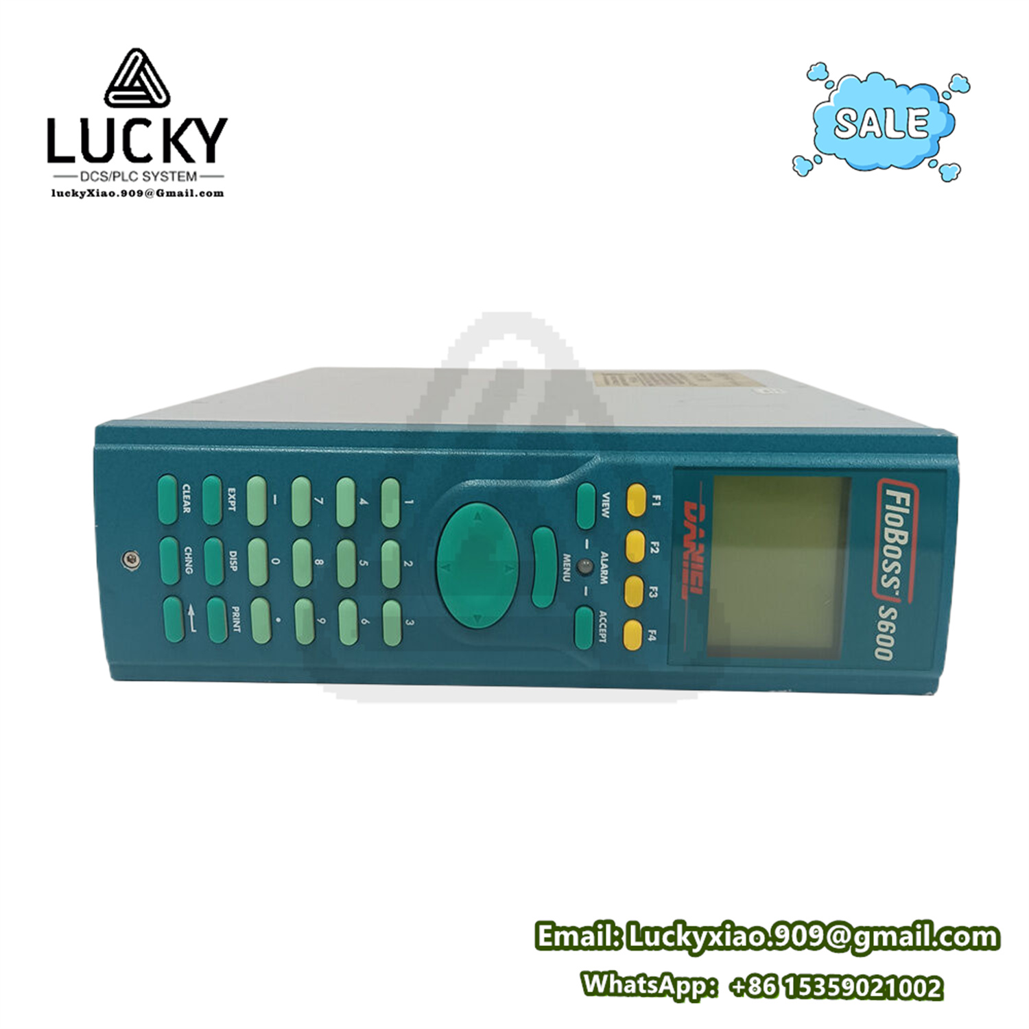
Introduction to EMEROSN FLOBOSS S600+
Product Description
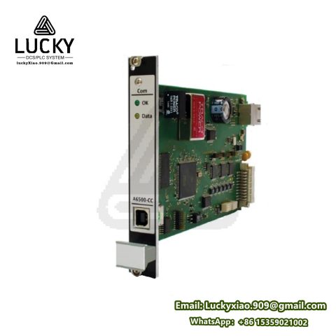
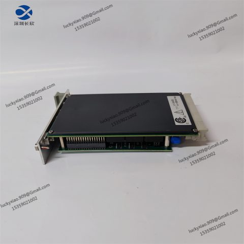
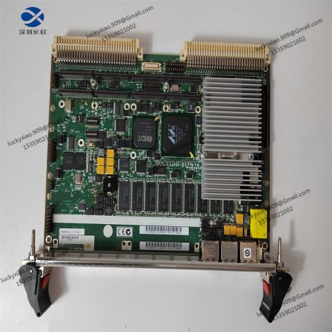
The EMEROSN FLOBOSS S600+ is a high – performance, panel – mount flow computer engineered for critical applications in the energy and industrial sectors. It is especially well – suited for fiscal measurement, custody transfer, batch loading, and meter proving, where accuracy and reliability are of utmost importance. This flow computer stands out for its ability to handle multi – stream and multi – station applications, enabling the simultaneous metering of both liquids and gases.
In the context of gas applications, the S600+ adheres to a wide range of international measurement standards, including AGA, ISO, GPA, GERG, and GOST. For liquid applications, it complies with API and ASTM standards. This broad standard support makes it a versatile choice for companies operating in different regions or industries with specific regulatory requirements. It can interface with a variety of flow meters such as coriolis, ultrasonic, turbine, positive displacement, orifice, venturi, annubar, and v – cone® meters, as well as Rosemount conditioning orifice plates. This compatibility allows for seamless integration into existing measurement systems.
Typical use cases span across various industries. In the oil and gas industry, it is used for accurate custody transfer of hydrocarbons between different parties, ensuring fair and precise accounting. In chemical plants, it controls and measures the flow of reactants and products during batch processes. For pipeline operators, it monitors and records the flow rates of liquids and gases over long distances, providing crucial data for system management and optimization.
Technical Parameters
- Processor and Calculation Precision:
-
- Equipped with a high – performance processor, the S600+ performs all metering calculations using 64 – bit (double) precision floating – point numbers. This ensures the highest level of accuracy in flow calculations, crucial for applications where even minor errors can lead to significant financial or operational consequences. It also helps in maintaining compliance with the latest API standards.
- Memory and Data Storage:
-
- Cumulative totals are stored in a tri – reg format, where data is saved in three separate memory locations. This redundant storage approach maximizes data integrity, protecting against potential data loss due to hardware failures or system glitches.
-
- It has enhanced data logging and archiving capabilities. For a ten – stream application, it can store up to 333 days of monthly, weekly, daily, and hourly reports. Additionally, it can record 50,000 events and 50,000 alarms. Support for FlowCal CFX files has been added, further enhancing data integrity and compatibility with other data management systems.
- Input and Output Interfaces:
-
- Analog Inputs:High – accuracy analog inputs with 24 – bit resolution offer an accuracy of ±0.005% of full scale (FS) at 23 °C. This allows for precise measurement of analog signals from sensors such as pressure and temperature transmitters.
-
- Digital Inputs/Outputs:Capable of handling digital signals from various sources, it can interface with flow switches, pulse – based sensors, and control actuators. The digital I/O is designed to be reliable and fast – responding, ensuring seamless integration with other components in the measurement system.
-
- HART Compatibility:It has 12 channels for HART transmitters, supporting up to 50 transmitters, including dual HART master functionality. This makes it easy to connect and communicate with HART – enabled sensors and devices, providing additional data and diagnostic capabilities.
- Communication Interfaces:
-
- Ethernet:Supports Ethernet communication, enabling high – speed data transfer to and from other network – connected devices. This is useful for integrating the S600+ into larger SCADA (Supervisory Control and Data Acquisition) systems or for remote monitoring and control. Protocols such as Ethernet/IP, Modbus TCP/IP, and PROFINET IRT are supported.
-
- Serial:Features both RS232 and RS485 serial ports. RS232 can be used for local programming and debugging, while RS485 is often used for connecting to field devices in a multi – drop configuration, such as remote I/O modules or other serial – based sensors. It supports protocols like Modbus RTU over RS485.
- Power Supply:
-
- Input power can be either 24V DC (with a wide – range tolerance of 18 – 36V DC) or 110/230V AC (85 – 264V AC, 50/60Hz), providing flexibility in different installation environments. Dual – input capability is also available in some configurations, enhancing power supply reliability.
- Environmental Ratings:
-
- Temperature Range:Operates within a wide ambient temperature range of – 10 °C to + 60 °C, making it suitable for use in various climates and industrial settings. It can withstand the temperature fluctuations commonly found in outdoor installations or industrial process areas.
-
- Humidity:Designed to operate in relative humidity levels ranging from 5 – 95% RH (non – condensing), meeting the requirements of IEC 60068 – 2 – 3.
-
- Protection Rating:The front panel has an IP40 protection rating, safeguarding against solid objects larger than 1.0 mm, while the backplane and expansion modules have an IP20 rating. This protection helps to ensure the long – term reliability of the device in industrial environments.
- Mechanical Dimensions:
-
- For the 19 – inch rack – mount version, it has a 3U height. The dimensions are 132mm (H) × 483mm (W) × 200mm (D), and it weighs approximately 4.5 kg in the base unit configuration, which can increase to up to 7.0 kg with full I/O expansion. The panel – mount option has specific cutout dimensions of 450mm × 120mm.
- Certifications:
-
- Holds CE (EMC: EN 61000 – 6 – 2, EN 61000 – 6 – 4) certification, ensuring compliance with electromagnetic compatibility standards. It also has UL 508 certification for industrial control equipment, ATEX Zone 2 certification for use in hazardous process environments, IEC 61508 SIL 2 for functional safety, and is RoHS 2.0 compliant, indicating it is free from hazardous substances.
Usage Methods
1. Installation
- Rack – Mount Installation:
-
- Mount the FLOBOSS S600+ in a standard 19 – inch industrial rack within a 3U slot. Use the provided mounting brackets and secure them with M6 screws, applying a torque of 8 Nm to prevent movement during normal operation or in the presence of vibration. Ensure that there is a minimum clearance of 50mm above and below the unit to facilitate proper airflow, especially important when expansion modules are in use as they can generate additional heat.
- Panel – Mount Installation:
-
- Utilize the optional panel – mount kit to attach the unit to a control panel. The cutout dimensions for the panel should be 450mm × 120mm. Apply a gasket between the unit and the panel to maintain the IP40 protection rating, protecting the internal components from dust and other contaminants.
- Environmental Considerations:
-
- Install the S600+ in a control cabinet where the ambient temperature does not exceed 60 °C under normal operating conditions. If the operating temperature is expected to reach up to 70 °C, forced – air cooling should be implemented. Avoid installing it near high – voltage cables, such as 480V motor wiring, or sources of electromagnetic interference (EMI) like variable – frequency drives (VFDs), as these can disrupt the accurate operation of the flow computer.
2. Wiring and Connection
- Power Wiring:
-
- DC Input:For 24V DC power input, connect the “V+” and “GND” terminals using 1.5mm² twisted – pair cable. Install a 5A inline fuse in the circuit to protect against overcurrent situations, which could potentially damage the device.
-
- AC Input:When using 110/230V AC power, connect the “L,” “N,” and “PE” terminals with 2.5mm² cable. Ensure proper grounding by connecting the “PE” (protective earth) terminal to a reliable earth ground, in accordance with safety standards such as IEC 60364.
- I/O Wiring:
-
- Digital Inputs:Connect sensors like limit switches and photoelectric sensors to the “DI” terminals using 0.75mm² 24V DC cable. Configure the PNP/NPN logic for the digital inputs via the front – panel DIP switches, depending on the type of sensors being used.
-
- Digital Outputs:Wire actuators such as relays and solenoids to the “DO” terminals. Ensure that the load current does not exceed 2A per channel. For higher – current loads, use a contactor to interface between the S600+ and the actuator.
-
- Analog Inputs:Use shielded twisted – pair cable (0.5mm²) for connecting 4 – 20mA or 0 – 10V analog signals from sensors such as pressure transducers and temperature transmitters. Ground the shield at the S600+ end to minimize electrical noise interference, which could affect the accuracy of the analog measurements.
-
- Analog Outputs:Connect the analog outputs to control valves or variable – speed drives (VSDs) using shielded cable. Calibrate the analog outputs via the device’s software to match the input requirements of the actuators, for example, setting the 4 – 20mA output range to correspond to 0 – 100% valve opening.
- Communication Wiring:
-
- Ethernet:Use Cat6 cable to connect the S600+ to a network switch or a human – machine interface (HMI). Assign a static IP address to the unit to ensure reliable communication, especially when using protocols like Modbus TCP/IP or Ethernet/IP.
-
- RS485 (Modbus RTU):Connect to field devices such as remote I/O modules or sensors using shielded twisted – pair cable. At the endpoints of the RS485 bus, add a 120Ω termination resistor to prevent signal reflections and ensure proper communication integrity.
3. Configuration and Programming
- Software Setup:
-
- Install the dedicated EMEROSN configuration software, which is compatible with Windows 10/11 operating systems, on a programming PC. Connect the PC to the S600+ using either the RS232 or Ethernet interface to establish communication.
-
- Create a new project within the software and select the FLOBOSS S600+ as the target device. Use the “Hardware Scan” function to automatically detect and import the unit’s hardware configuration, simplifying the setup process.
- Logic and Control Programming:
-
- Flow Calculation Configuration:Define the type of flow meters connected to the S600+ and configure the appropriate flow calculation algorithms based on the fluid properties (gas or liquid), flow meter characteristics, and measurement standards (e.g., API for liquids, AGA for gases).
-
- Data Logging Setup:Specify the data points to be logged, such as flow rates, temperatures, pressures, and other relevant process variables. Set the logging intervals, which can range from 1 – 3600 seconds, depending on the application requirements. Configure the data export settings to transfer logged data to external systems like a SCADA server or a cloud – based storage solution, for example, using MQTT protocol for cloud connectivity.
-
- Alarm and Event Configuration:Define alarm conditions based on process variable thresholds. For example, set an alarm to trigger if the flow rate exceeds a certain maximum value or if the temperature of a fluid being measured goes out of the normal operating range. Configure event logging to record significant events such as meter failures, communication errors, or changes in control settings.
- Testing and Validation:
-
- I/O Functionality Testing:Use the software’s “Force I/O” tool to test the input and output functionality of the S600+. For example, force a digital input to a high state and verify that the corresponding digital output activates as expected. Similarly, inject a known analog input signal and check if the device correctly measures and processes the value.
-
- Flow Meter Simulation:Simulate different flow conditions by adjusting the input signals to the S600+ as if they were coming from real – world flow meters. This can be done using a signal generator or by manually setting values within the configuration software. Validate the accuracy of the flow calculations and the response of any control algorithms implemented.
-
- Communication Testing:Send test commands to connected devices over the communication interfaces (e.g., send a Modbus read command to a remote I/O module or an Ethernet – connected HMI) and verify that the data is correctly transmitted and received. Check for any communication errors or timeouts.
4. Operation and Maintenance
- Startup Verification:
-
- Power on the FLOBOSS S600+ and observe the status LED. A solid green LED indicates normal operation, a flashing yellow LED signals a warning condition, and a solid red LED indicates a fault. Use the diagnostic dashboard within the configuration software to troubleshoot any faults that may occur, such as communication failures with connected devices, power supply issues, or problems with the internal hardware components.
- Real – Time Monitoring:
-
- Connect the S600+ to an HMI or use the configuration software’s “Live View” interface to monitor real – time process variables, including flow rates, pressures, temperatures, and the status of digital inputs and outputs. Set up visual and audible alarms for abnormal conditions, such as a high – flow alarm or a low – pressure alarm.
-
- Regularly review the logged data to identify trends and patterns in the flow measurements. Analyze the data to detect any potential issues, such as a gradual decrease in flow rate over time, which could indicate a blockage in the pipeline or a problem with the flow meter.
- Maintenance:
-
- Monthly Maintenance:Inspect all wiring connections for tightness. Loose connections can lead to intermittent communication problems or inaccurate measurements. Check for any signs of overheating, such as discolored wires or components. Clean the ventilation slots of the unit using compressed air at a pressure of ≤40 psi to remove dust, which can accumulate and affect the device’s cooling performance.
-
- Quarterly Maintenance:Back up the project and configuration files to a secure server. This ensures that in the event of a hardware failure or accidental data loss, the device can be quickly restored to its previous working state. Verify the battery backup functionality by temporarily disconnecting the power supply and checking that the data is retained as expected.
-
- Annual Maintenance:Check for available firmware updates on the EMEROSN support portal. Download and install the latest firmware via the Ethernet interface to access new features, improve performance, and address any security vulnerabilities. Calibrate the analog inputs and outputs using a precision signal generator to ensure continued accuracy in measurements.
System Introduction
The EMEROSN FLOBOSS S600+ functions as a central component in industrial flow measurement and control systems, integrating several key functional layers to ensure accurate and reliable operation:
1. Sensing Layer
The S600+ interfaces with a wide variety of sensors in the field. It can receive digital pulse signals from flow meters like turbine meters, which generate pulses proportional to the volume of fluid passing through. For continuous – variable measurements, it connects to analog sensors such as pressure transmitters (4 – 20mA or 0 – 10V output) and temperature sensors. In an oil pipeline, for example, it reads pressure and temperature values from sensors installed at regular intervals. These measurements are crucial for compensating the flow rate calculations, as changes in pressure and temperature can affect the density and viscosity of the fluid, thus influencing the flow volume.
2. Processing Layer
Once the sensor data is received, the high – performance processor in the S600+ springs into action. It uses 64 – bit double – precision floating – point calculations to perform complex flow rate computations. For gas flow measurement, it may apply equations based on standards like AGA8 to account for factors such as gas composition, compressibility, and flow regime. In liquid flow applications, it adheres to API standards, considering factors like liquid density, viscosity, and the characteristics of the flow meter. It also executes logic for data logging, alarm generation, and control actions. For instance, if the measured flow rate exceeds a pre – set maximum value, it can trigger an alarm and initiate a control action, such as closing a control valve in the pipeline.
3. Communication Layer
This layer enables the S600+ to interact with other components in the industrial ecosystem. It can communicate with upstream systems like SCADA servers via Ethernet – based protocols such as Modbus TCP/IP or Ethernet/IP. This allows plant operators to monitor and control the flow measurement process from a central location. It also communicates with downstream devices, such as remote I/O modules, which can be used to expand the I/O capabilities of the S600+ or to interface with additional sensors and actuators in the field. For example, it can send commands to a remote I/O module to activate a pump based on the flow rate measurements.
4. Actuation Layer
In some applications, the S600+ is directly connected to actuators. It can control the opening and closing of valves, for example, to regulate the flow rate of a fluid. In a batch – loading process, it can send digital signals to solenoid valves to start and stop the flow of liquid into a storage tank. The control signals are generated based on the flow rate calculations and the setpoints defined in the control logic. If the target volume of liquid has been reached, the S600+ will send a signal to close the valve, ensuring accurate batch –

There are no reviews yet.