

_副本")
_副本")
_副本")
Product Description
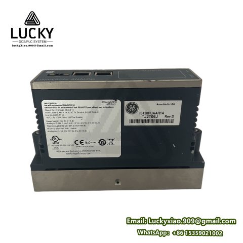
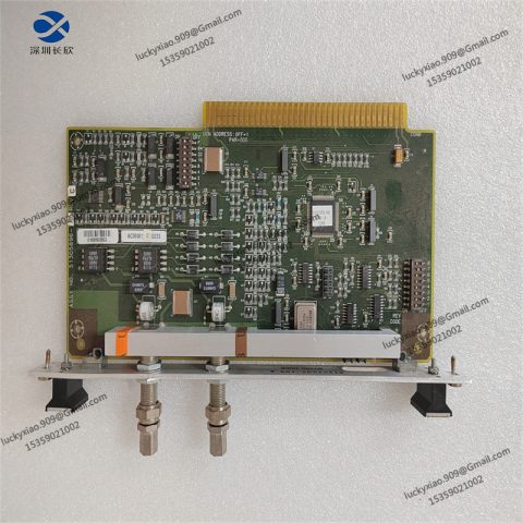
GE DS200DCFBG1BJB is a high-reliability DC field control board designed specifically for industrial drive systems, with a primary focus on supporting the operation of DC motors in heavy-duty industrial environments. As a critical component in GE‘s Speedtronic control system lineup, it is engineered to deliver precise regulation of DC motor fields, ensuring stable speed and torque control across a wide range of industrial applications.
The board features a ruggedized design, built to withstand the demanding conditions of industrial settings, including temperature variations, electrical interference, and mechanical vibrations. Its compact form factor allows for easy integration into existing drive cabinets, making it suitable for both new installations and system upgrades. With a focus on durability and performance, it adheres to strict industry standards, ensuring compatibility with GE‘s drive systems and reliable operation in critical processes such as steel manufacturing, mining, and material handling.
Technical Parameters
- Operating Voltage: 125V DC ±10% (field excitation)
- Output Current Range: 0-300A (continuous), 600A (peak for 10 seconds)
- Operating Temperature Range: 0°C to 60°C
- Storage Temperature Range: -40°C to 85°C
- Control Signal Input: 4-20mA (analog setpoint)
- Feedback Signals: DC current shunt (0-50mV), speed feedback (tachometer or encoder)
- Protection Features: Overcurrent protection, overvoltage protection, overtemperature shutdown
- Communication Interface: RS-485 (Modbus RTU) for system integration
- Dimensions: 220mm × 160mm × 40mm (length × width × height)
- Weight: Approximately 500g
- Certifications: CE, UL, IEC 61800-5-1
Usage Method
- Installation: Mount the DS200DCFBG1BJB board in the designated slot within the drive cabinet using the provided mounting screws. Ensure the cabinet is properly ventilated to maintain operating temperatures within the specified range. Connect the 125V DC power supply to the board’s power terminals, following the polarity markings in the user manual.
- Wiring Connections: Link the DC motor’s field winding to the output terminals of the board. Connect the analog setpoint signal (4-20mA) from the controller to the input terminal. Attach current shunt feedback and speed feedback devices to their respective ports. Establish communication with the main control system via the RS-485 interface using shielded twisted-pair cable.
- Configuration: Use GE‘s DriveTools SP software to configure the board parameters. Set the current limit, voltage range, and feedback type according to the motor specifications and application requirements. Calibrate the analog input and feedback signals to ensure accurate control. Save the configuration to the board’s non-volatile memory.
- Operation and Monitoring: Power on the drive system and monitor the board’s status via the software interface or front-panel indicators. Check for normal operation, including stable current output and correct response to setpoint changes. In case of faults (e.g., overcurrent), the board will trigger a shutdown and display an error code—refer to the manual for troubleshooting steps.
- Maintenance: Perform periodic inspections to ensure all connections are tight and free from corrosion. Clean dust from the board’s surface using compressed air. Verify protection settings annually using calibration tools. Update the firmware via the RS-485 interface when newer versions are available to enhance performance.
System Introduction
GE DS200DCFBG1BJB is a key component of GE‘s DC drive systems, which are widely used in industrial applications requiring precise motor control. The system integrates the field control board with a main controller, operator interface, and protection devices to form a complete drive solution.
In this system, the DS200DCFBG1BJB regulates the DC motor’s field current based on the analog setpoint, adjusting the motor’s speed and torque accordingly. It continuously monitors current, voltage, and temperature, activating protective shutdowns when abnormal conditions are detected to prevent damage to the motor or board.
The board communicates with the main controller via Modbus RTU, enabling centralized monitoring and control of multiple drives in a plant-wide system. This integration allows for synchronized operation of motors in complex processes, such as conveyor lines or rolling mills, ensuring consistent performance and productivity.

There are no reviews yet.