

_副本(1)")
Easy Guide: GE DS200TCQCG1BGF Turbine Control Module
1. Product Overview
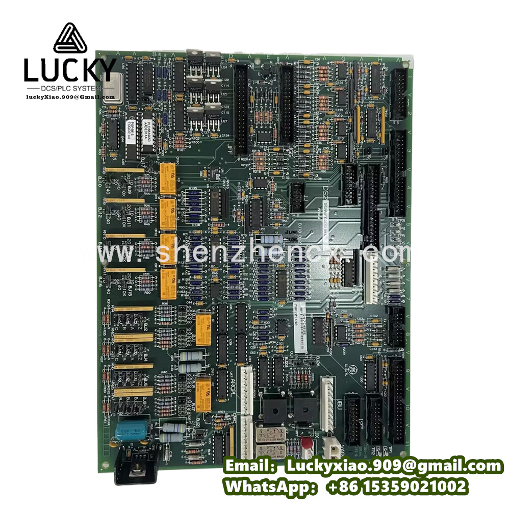
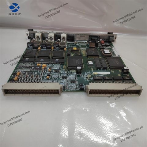
GE DS200TCQCG1BGF is a specialized turbine control module designed for GE’s Speedtronic Mark V and Mark VI control systems. Acting as the “control center” for gas and steam turbines, it processes critical operational data (like speed, pressure, and vibration) and sends precise commands to turbine components—ensuring smooth startup, stable operation, and safe shutdown of turbines in power plants and industrial facilities.
Its core role is to be the “turbine’s guardian”: It continuously monitors key turbine parameters, compares them with preset safety and performance standards, and adjusts components like fuel valves or guide vanes in real time. For example, when a gas turbine’s speed exceeds the safe limit, the module immediately reduces fuel supply to lower the speed, preventing equipment damage or accidents.
Key advantages that make it indispensable in turbine control:
-
Turbine-Specific Design: Optimized for turbine control logic (e.g., speed regulation, load distribution), it works more efficiently than general-purpose control modules.
-
Fast Response: Equipped with a high-speed processing chip, it responds to parameter changes in less than 10ms—critical for avoiding turbine overspeed or overpressure.
-
High Reliability: Uses industrial-grade components and redundant circuits, with a mean time between failures (MTBF) of over 100,000 hours—suitable for 24/7 continuous operation.
-
Easy Upgradability: Compatible with both legacy Mark V and modern Mark VI systems, allowing plants to upgrade control capabilities without replacing the entire turbine control system.
Practical example: In a combined-cycle power plant, the DS200TCQCG1BGF module controls a 100MW gas turbine. During startup, it gradually increases fuel supply to raise the turbine speed from 0 to 3000 rpm (synchronous speed). Once connected to the grid, it adjusts fuel input based on grid load demands, keeping the turbine’s output stable at the required level.
2. Key Technical Specifications
|
Specification Category
|
Details
|
|---|---|
|
Typical Applications
|
Gas turbines, steam turbines, combined-cycle power plants, and industrial turbine-driven pumps/compressors
|
|
Core Functions
|
Speed regulation, load control, startup/shutdown sequence control, fault detection, and emergency protection
|
|
Input/Output (I/O) Capacity
|
16 digital inputs, 8 digital outputs, 4 analog inputs (for speed/pressure signals), 2 analog outputs (for valve control)
|
|
Performance
|
Response time: ≤10ms; Speed control accuracy: ±0.1% of rated speed; Load control accuracy: ±0.5% of rated load
|
|
Communication Interface
|
Compatible with GE’s Turbine Control Network (TCN); Supports RS-485 and Ethernet/IP (for connection to HMI/SCADA)
|
|
Power Supply
|
24V DC ±15%; Power consumption: ≤12W (normal operation)
|
|
Protection Features
|
Over-voltage protection (≥36V DC); Short-circuit protection; ESD protection (±4kV contact)
|
|
Environmental Conditions
|
Operating temperature: 0℃–65℃; Relative humidity: 5%–95% (no condensation); Protection class: IP20 (when installed in cabinet)
|
|
Physical Specifications
|
Dimensions: 180mm×110mm×45mm (L×W×H); Weight: ~750g; Mounting: Speedtronic Mark V/VI standard rack
|
|
Certifications
|
UL, CE, IEC 61508 (SIL 2), ISO 9001
|
3. System Integration Guide
DS200TCQCG1BGF is the core of GE’s turbine control system. Integrating it requires matching with turbine sensors, actuators, and Speedtronic controllers. The process is tailored to turbine operation needs, with clear steps and safety priorities:
3.1 Integration Steps (with Safety Tips)
-
Ensure Turbine Safety: Lock the turbine’s main fuel valve and emergency stop button to prevent accidental startup during integration. Confirm the turbine is in “Maintenance Mode” via the control panel.
-
Module Installation: Insert the DS200TCQCG1BGF into the dedicated slot of the Mark V/VI rack (labeled “Turbine Control”). Push until it clicks to ensure a tight connection with the backplane.
-
Wiring Connections: Connect turbine sensors: Link speed probes (to “Speed Input” terminals), pressure transmitters (to “Analog Input” terminals), and vibration sensors (to dedicated “Protection Input” terminals).
-
Connect actuators: Wire fuel control valves and guide vane motors to the module’s “Analog Output” and “Digital Output” terminals.
-
Connect power and communication: Link 24V DC power to the “Power” terminal, and connect the Ethernet port to the Speedtronic controller and HMI.
-
Parameter Configuration: Use GE’s Turbine Control Studio software to set key parameters: Turbine basic info: Rated speed (e.g., 3000 rpm), rated load (e.g., 100MW), and fuel type (e.g., natural gas).
-
Safety thresholds: Overspeed limit (e.g., 110% of rated speed), overpressure limit (e.g., 120% of rated pressure).
-
Control logic: Startup sequence (e.g., preheating time, speed rise rate) and load adjustment curve.
-
Test & Commissioning: Dry test: Without starting the turbine, send simulated signals (e.g., speed = 2500 rpm) via software to confirm the module sends correct valve adjustment commands.
-
Idle test: Start the turbine in idle mode (no load) and verify the module maintains speed at 1500 rpm (idle speed) stably.
-
Load test: Gradually increase the load to 50MW and 100MW, checking if the module adjusts fuel supply smoothly to match load demands.
3.2 Daily Maintenance Tips
-
Daily Check: Monitor the module’s status LEDs—steady green “Run” = normal, flashing red = fault. Check HMI for turbine parameters (speed, load) to ensure they are within normal ranges.
-
Weekly Inspection: Clean the module’s ventilation holes with a soft brush to prevent overheating. Check wiring terminals for looseness (turbine vibration can cause connections to shift).
-
Monthly Backup: Use Turbine Control Studio to back up the module’s configuration parameters and control logic to a secure storage device.
-
Quarterly Calibration: Calibrate speed probes and pressure sensors with standard tools, then verify the module’s reading accuracy via HMI.
-
Fault Handling: If a fault occurs (e.g., “overspeed alarm”), first trigger the turbine’s emergency stop. Use software to read the fault code (e.g., “F003” = speed sensor fault) for targeted repairs.
4. Recommended GE Related Models (Different Series)
GE offers diverse turbine control and industrial automation modules to meet different equipment and scenario needs. Below are practical models from other GE series:
|
Model
|
Series
|
Key Features & Application Scenarios
|
|---|---|---|
|
GE IC695CPU315
|
RX3i
|
General-purpose PLC CPU module. Suitable for controlling turbine auxiliary systems (e.g., cooling water pumps, lubricating oil systems) with its 1.2GHz dual-core processor.
|
|
Mark VIe Analog I/O
|
Precision analog input module. Collects turbine temperature, pressure, and vibration signals for the DS200TCQCG1BGF module—ideal for data-intensive turbine monitoring.
|
|
|
GE DS3800HISB1A1A
|
Legacy turbine control module. Used for upgrading older Mark IV systems in power plants that haven’t replaced their turbines but need improved control reliability.
|
|
|
GE IC698CPE030
|
PACSystems RXi
|
Ruggedized controller for outdoor turbines. With IP67 protection, it’s suitable for offshore wind turbines or remote gas turbine stations exposed to harsh weather.
|
|
GE DS200TCCAG1A
|
Mark VI Turbine I/O
|
High-density digital I/O module. Expands the DS200TCQCG1BGF’s I/O capacity to control multiple turbine accessories (e.g., 20+ valves) in large-scale turbine systems.
|
|
GE IS420ESWBH2A
|
Mark VIe Digital I/O
|
Switch input module. Monitors turbine safety switches (e.g., emergency stop buttons, door interlocks) and sends status signals to the main control module.
|
|
GE IC695PSD040
|
RX3i Power Supply
|
Redundant power supply module. Ensures stable 24V DC power for the DS200TCQCG1BGF and other turbine control modules—critical for preventing power-related faults.
|
There are no reviews yet.