





GE IS200AEADH4ADA Product Overview
IS200AEADH4ADA Product Introduction
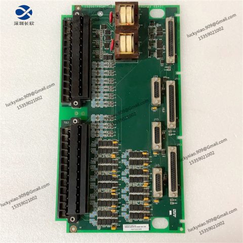
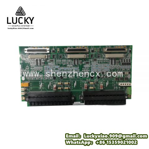
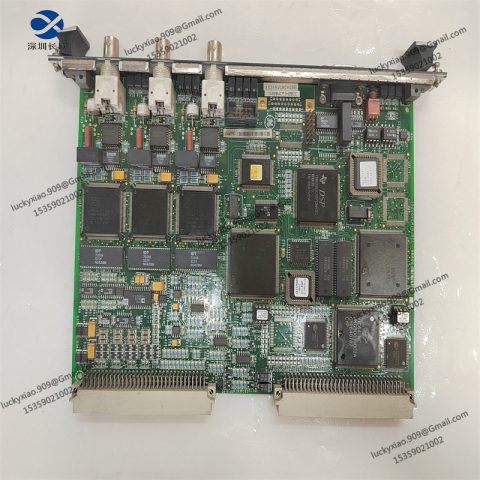
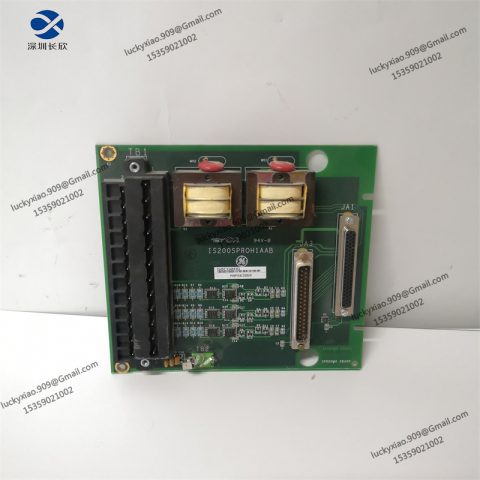
The GE IS200AEADH4ADA carries the generator-side wiring of a Speedtronic Mark VI turbine control rack. It lands exciter feedback, breaker permissives and protection status on numbered screw terminals, then switches those signals through eight on-board relays. This board belongs to the AEAD family, built for the high-energy signals that connect a generator to the grid.
IS200AEADH4ADA Technical Specifications
The board earns its design from connector density, relay count and heat. The table below lays out the hardware you will see when you open the cabinet.
|
Parameter
|
Value
|
|---|---|
|
Part Number
|
IS200AEADH4ADA
|
|
Series
|
GE Speedtronic Mark VI / Mark VIe
|
|
Function
|
Exciter and generator feedback input and relay board
|
|
Terminal Strips
|
Three vertical strips, twelve positions each
|
|
On-board Relays
|
Eight relay assemblies
|
|
Stab-on Connectors
|
Four along one long edge, four along one short edge
|
|
Rack Interface
|
Two plug connectors and one right-angle terminal strip
|
|
Heat Management
|
Two heat sinks for on-board drive losses
|
|
Components
|
High-voltage capacitors, wire-wound resistors, ICs
|
|
Prime Movers
|
Gas and steam turbine generator sets
|
Why the Generator Side Needs a Different Board
The turbine side of the rack handles small signals — millivolts from probes, degrees from RTDs. The generator side works with transducers measuring megawatt-scale machines and with permissives that decide whether a breaker closes. A wrong reading here does not cause a nuisance alarm; it causes a synchronization out of step or a trip at the wrong moment.
The eight relays form the isolation boundary. They keep the plant-side currents off the low-voltage logic, and they carry the dry contacts that the protection scheme expects. These relays see the most switching of any component on the board, which is why a plant that tracks relay cycles keeps a healthier spares bin than one that does not.
The capacitors and wire-wound resistors handle the energy that generator circuits store. Field discharge and excitation transients need a place to go, and the board gives those components room to work. That layout choice explains the two heat sinks: this board dissipates real power, and covering it during a cabinet visit blocks the airflow it needs.
Wiring the Board in Practice
You start any work on this board by making the circuit safe. Exciter and field circuits hold energy that outlives the control power, so you open the breaker, discharge the field, and apply a lockout before you touch a terminal. Treating this card like the low-voltage boards beside it is the one mistake that turns a routine swap into an incident.
You then land every wire by the numbers. Each of the three strips carries twelve numbered positions, and the design drawing maps each number to a signal. When you remove the harness, you photograph each strip first; with thirty-six terminals across three strips, a single misplaced wire costs an hour of chasing a feedback that only fails under load.
You seat the stab connectors by hand. The spade contacts along the two edges join the board to the rack harness, and a half-seated stab produces an intermittent that teases you — it works with the door open and fails with it shut. Pressing each contact home before power-up takes ten seconds and prevents a day of hunting.
Reading the Board’s Health
The failures on this family follow a pattern, and you can catch most of them before they bite. Relays wear: after years of switching, a contact grows a resistive film that makes a permissive look open even though the armature moved. A multimeter across the contact tells you the truth before you order a new assembly.
Capacitors dry. The high-voltage parts have a design life in years, and a unit that has run through two decades of cycling is overdue for inspection. A bulged case or a weeping seal reads at a glance and should never wait for the next outage.
Resistors drift, and drift in the wire-wound references shifts the threshold the protection logic compares. The rack software flags this in yearly diagnostics if you run them. When a synchronization fails with no obvious cause after an exciter visit, you check this board before you touch the governor — the part you just worked on is the likeliest offender.
Application Areas
This family lives at the meeting point of turbine control and the electrical grid.
-
Exciter feedback loops — field voltage and current signals into the regulator.
-
Breaker permissives and sync checks — interlocks that gate a close command.
-
Generator protection handshakes — status exchanged with the protection relay scheme.
-
Combined-cycle and cogeneration — generator-side wiring on steam and gas packages.
Whatever the unit, the board decides whether the machine reports itself as safely on the grid.
Recommended Same-series Boards
The Mark VI exciter and termination family covers the rest of the generator and protection chain. The boards below each handle a part of the job this one leaves untouched.
-
IS200AEADH1A — Earlier AEAD revision offering the same input and relay termination role.
-
IS200EDCFG1A — Exciter DC feedback board that measures field voltage and current.
-
IS200TGENH1AAA — Generator terminal board for stator and rotor protection wiring.
-
IS200TREGH1BDB — Trip emergency termination board for the main trip solenoid.
-
IS200TPROH1BCB — Protective termination board carrying trip relays and surge MOVs.
-
IS200TVIBH2BBB — Vibration termination board for probe and key-phasor channels.



There are no reviews yet.