


Detailed Introduction to Toshiba HC422B
1. Product Description
The Toshiba HC422B is a high-performance, industrial-grade incremental encoder developed by Toshiba Corporation, tailored for precision motion control applications. As a core component in position and speed feedback systems, it converts mechanical rotational or linear motion into electrical pulse signals, enabling real-time monitoring and precise regulation of equipment movement.
Designed for harsh industrial environments, the HC422B excels in scenarios requiring high accuracy and reliability. For example:
- In CNC machining centers, it provides real-time speed and position feedback for spindle and feed axes, ensuring machining precision within ±0.001mm;
- In robotic arms, its compact design fits into tight mechanical structures, delivering stable pulse signals to control joint rotation angles and movement smoothness;
- In conveyor systems for logistics or manufacturing, it monitors belt speed and cumulative displacement, preventing over-speed or position deviation issues.
With its robust construction and anti-interference capabilities, the HC422B reliably operates in conditions with vibration, temperature fluctuations, and electrical noise—making it a trusted choice for automotive, aerospace, and precision manufacturing industries.
2. Product Technical Specifications
The HC422B’s specifications are optimized for industrial motion control, balancing accuracy, durability, and compatibility. Key parameters are categorized below:
2.1 Core Performance
|
Parameter
|
Specification
|
|
Encoding Type
|
Incremental (A, B, Z phases; Z phase = 1 pulse/revolution for zero reference)
|
|
Resolution
|
100–5,000 pulses per revolution (PPR); customizable for specific needs
|
|
Output Signal Format
|
Differential line driver (RS422); compatible with single-ended TTL (optional)
|
|
Signal Duty Cycle
|
50% ±10% (ensures uniform pulse timing)
|
|
Maximum Response Frequency
|
100 kHz (supports high-speed motion up to 6,000 RPM for 100 PPR models)
|
|
Accuracy
|
Phase deviation ≤ ±1°; pulse error ≤ ±0.1% of full resolution
|
2.2 Mechanical & Environmental Ratings
|
Parameter
|
Specification
|
|
Shaft Diameter
|
6mm or 8mm (standard); stainless steel (SUS304) for corrosion resistance
|
|
Shaft Load Capacity
|
Radial: 20N; Axial: 10N (prevents damage from mechanical stress)
|
|
Operating Temperature
|
-20°C to +85°C (wide range for indoor/outdoor industrial use)
|
|
Storage Temperature
|
-40°C to +100°C
|
|
Protection Level
|
IP65 (dust-tight, water-resistant; suitable for wet or dusty workshops)
|
|
Vibration Resistance
|
10–2,000 Hz, 50 m/s² (IEC 60068-2-6 standard)
|
|
Shock Resistance
|
500 m/s² (11ms duration; IEC 60068-2-27 standard)
|
2.3 Electrical Specifications
|
Parameter
|
Specification
|
|
Power Supply
|
DC 5V ±5% (stable voltage for consistent signal output)
|
|
Current Consumption
|
≤30mA (low power to reduce heat generation)
|
|
Insulation Resistance
|
≥100 MΩ (500V DC; between terminals and housing)
|
|
Dielectric Strength
|
500V AC for 1 minute (no breakdown or leakage)
|
|
Output Load Resistance
|
100–1,000 Ω (for RS422 differential signals)
|
3. Usage Instructions
Proper installation, wiring, and calibration are critical to maximizing the HC422B’s performance. Follow these steps for safe and effective operation:
3.1 Pre-Installation Preparation
- Compatibility Check: Confirm the encoder’s resolution (PPR) and output format (RS422/TTL) match your motion controller’s requirements. For example, a 1,000 PPR encoder is suitable for applications needing 0.36° angular resolution.
- Inspection: Visually check the encoder for physical damage (e.g., cracked housing, bent shaft). Verify that accessories (mounting brackets, coupling, cables) are included and intact.
- Environmental Prep: Ensure the installation location meets the HC422B’s environmental ratings (e.g., avoid direct water spray if using IP65 models; keep away from strong magnetic fields).
3.2 Mechanical Installation
- Shaft Alignment:
-
- Use a flexible coupling to connect the encoder shaft to the target machine shaft (e.g., CNC axis). Misalignment should not exceed 0.1mm (radial) and 0.05mm (axial) to prevent shaft wear.
-
- Secure the encoder to the machine frame using the provided mounting bracket. Tighten screws to 0.5–1.0 N·m (avoid over-tightening, which may damage the housing).
- Shaft Load Check: Ensure the radial/axial load on the encoder shaft does not exceed 20N/10N. Use a load gauge to verify if necessary.
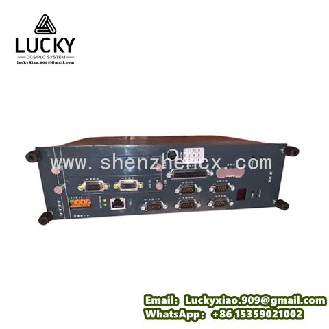
3.3 Wiring Connection
The HC422B uses a standard 8-pin M12 connector (or terminal block, optional) for signal and power. Follow this wiring diagram for RS422 differential output:
|
Pin Number
|
Signal Name
|
Description
|
Connection Target
|
|
1
|
Vcc
|
Power Supply (+5V DC)
|
Controller’s +5V terminal
|
|
2
|
GND
|
Power Ground
|
Controller’s GND terminal
|
|
3
|
A+
|
Channel A (differential positive)
|
Controller’s A+ input
|
|
4
|
A-
|
Channel A (differential negative)
|
Controller’s A- input
|
|
5
|
B+
|
Channel B (differential positive)
|
Controller’s B+ input
|
|
6
|
B-
|
Channel B (differential negative)
|
Controller’s B- input
|
|
7
|
Z+
|
Zero Reference (differential positive)
|
Controller’s Z+ input
|
|
8
|
Z-
|
Zero Reference (differential negative)
|
Controller’s Z- input
|
Wiring Notes:
- Use twisted-pair shielded cables (24 AWG) to reduce electromagnetic interference. The shield should be grounded at one end (preferably the controller side) to avoid ground loops.
- Keep encoder cables at least 30cm away from high-voltage power cables (e.g., motor wires) to prevent signal distortion.
3.4 Calibration & Testing
- Power-Up Check: Apply DC 5V power. The encoder’s LED indicator (if equipped) should light up (green = normal; red = fault).
- Zero Reference Calibration:
-
- Manually rotate the machine shaft until the Z-phase pulse is detected (check via the controller’s diagnostic tool). Mark this position as the “zero point” for the system.
- Accuracy Verification:
-
- Rotate the shaft 360° at a constant speed. The controller should count pulses equal to the encoder’s PPR (e.g., 1,000 pulses for 1,000 PPR). A deviation of more than ±1 pulse indicates misalignment or wiring issues.
-
- Test high-speed operation (up to the encoder’s max frequency). Ensure no pulse loss occurs (verify via controller’s error logs).
3.5 Routine Maintenance
- Monthly Inspection: Check for loose mounting screws, cable damage, or oil/dust accumulation on the encoder. Clean the housing with a dry, lint-free cloth.
- Quarterly Calibration: Re-verify zero position and pulse accuracy, especially after machine maintenance or vibration events.
- Annual Service: Replace aging cables (every 2–3 years) and inspect the shaft for wear. For harsh environments, check IP65 sealing integrity.
4. System Introduction
The Toshiba HC422B functions as the “sensory core” of motion control systems, integrating with controllers, drives, and mechanical components to form a closed-loop feedback system. Below is its role in a typical industrial setup:
4.1 System Architecture
A standard motion control system with the HC422B includes four key layers:
- Mechanical Layer:
-
- The HC422B is mounted on the machine’s moving part (e.g., CNC axis, robotic joint). It directly measures the part’s rotation or linear motion (via a linear guide adapter).
- Sensing Layer:
-
- The HC422B converts mechanical motion into A/B/Z phase electrical pulses. Channel A and B pulses are 90° out of phase, enabling the controller to determine direction (clockwise/counterclockwise) and speed; the Z pulse provides a reference zero point.
- Control Layer:
-
- A motion controller (e.g., Toshiba TMPM375 microcontroller, or third-party PLCs like Siemens S7-1200) receives the encoder’s pulses. It calculates real-time speed (based on pulse frequency) and position (based on pulse count), then sends control signals to the drive.
- Actuation Layer:
-
- A motor drive (e.g., servo drive) adjusts the motor’s speed or torque according to the controller’s commands. The encoder’s feedback ensures the motor operates exactly as instructed (closed-loop control), eliminating position/speed errors.
4.2 System Advantages
- High Precision: With resolution up to 5,000 PPR and phase deviation ≤ ±1°, the HC422B enables sub-millimeter or sub-degree control—critical for precision machining or robotic assembly.
- Reliability in Harsh Environments: IP65 protection, wide temperature range, and anti-vibration design reduce downtime in industrial settings (MTBF ≥ 50,000 hours).
- Flexible Integration: Compatible with most motion controllers and drives (supports RS422/TTL output), making it easy to upgrade existing systems without replacing other components.
- Cost-Effectiveness: Compared to absolute encoders, the HC422B offers lower cost while meeting the accuracy needs of 80% of industrial applications (e.g., conveyors, general-purpose CNC machines).
4.3 Typical Application Example: CNC Milling Machine
In a CNC milling machine, the HC422B is installed on the X, Y, and Z axes:
- When the operator inputs a machining path, the controller calculates the required axis positions.
- The HC422B sends pulse signals to the controller as the axes move, updating real-time position data.
- If the axis deviates from the target position (e.g., due to motor load), the controller adjusts the drive signal to correct the error—ensuring the milled part meets design specifications.
Conclusion
The Toshiba HC422B incremental encoder combines precision, durability, and compatibility to meet the demands of modern industrial motion control. Whether used in CNC machines, robots, or conveyor systems, it provides reliable feedback that enhances equipment performance, reduces errors, and lowers maintenance costs. By following proper installation and maintenance procedures, users can maximize the HC422B’s lifespan and unlock its full potential in their applications.


There are no reviews yet.