

_副本")
_副本")
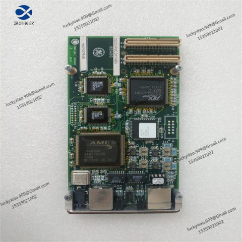
Detailed Introduction to DS200SDCIG2ABA GE Interface Module
1. Product Description
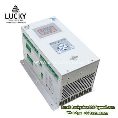
The DS200SDCIG2ABA is a high-performance, specialized interface module developed by GE for the Speedtronic Mark VIe Distributed Control System (DCS)—a leading control solution for gas turbines, steam turbines, and combined-cycle power plants. As a critical component in turbine control architectures, this module serves as the “data bridge” between the Mark VIe controller (e.g., IS420UCSBH1A) and turbine-specific sensors/actuators, enabling real-time data transmission, signal conditioning, and control command execution.
Unlike generic interface modules, the DS200SDCIG2ABA is engineered to meet the rigorous demands of power generation environments, with a focus on signal integrity and fault tolerance. It specializes in processing analog and digital signals from turbine auxiliary systems—such as lubricating oil pressure sensors, temperature transducers, and valve position feedback devices—converting raw signals into standardized data formats compatible with the Mark VIe controller. This ensures precise monitoring of turbine health parameters and reliable execution of control strategies (e.g., speed regulation, load balancing).
Key differentiators include its modular design (compatible with Mark VIe’s common backplane), built-in diagnostic capabilities, and compliance with industrial standards (IEC 61508 for functional safety, IEEE 1588 for time synchronization). It is widely deployed in utility power plants, industrial cogeneration facilities, and offshore energy platforms, where it contributes to turbine efficiency, operational safety, and reduced downtime.
2. Product Technical Specifications
|
Specification Category
|
Details
|
|
Signal Input/Output (I/O) Capabilities
|
– Analog Inputs (AI): 8 channels, 16-bit resolution, 4-20 mA DC (isolated, ±0.1% full-scale accuracy)- Digital Inputs (DI): 16 channels, dry contact (24 VDC, 5 mA max current; 10 ms debounce time)- Digital Outputs (DO): 8 channels, relay outputs (SPDT, 2 A @ 250 V AC / 30 V DC)- Signal Conditioning: Built-in signal filtering (low-pass, 50/60 Hz notch) to reduce electromagnetic interference (EMI)
|
|
Electrical Parameters
|
– Power Supply: 5 V DC (from Mark VIe backplane); 24 V DC (external, for relay outputs)- Power Consumption: 3.5 W (typical); 5 W (max, with all relays energized)- Isolation: Channel-to-channel isolation (500 V AC rms, 1 minute); power-to-signal isolation (1 kV AC rms, 1 minute)
|
|
Performance Metrics
|
– Data Update Rate: 10 ms per channel (AI/DI); 5 ms per channel (DO command execution)- Time Synchronization: Compliant with IEEE 1588 PTP (Precision Time Protocol), ±1 µs synchronization accuracy with Mark VIe controller- Calibration: Factory-calibrated (±0.05% drift per year); field-calibratable via GE ToolboxST software
|
|
Physical & Environmental
|
– Dimensions: 160 mm (W) × 220 mm (H) × 80 mm (D) (fits Mark VIe standard chassis)- Weight: 1.2 kg- Operating Temperature: -40°C to +70°C- Storage Temperature: -55°C to +85°C- Relative Humidity: 5-95% (non-condensing, no frost)- Enclosure Rating: IP20 (for rack-mounted chassis installation)- Vibration Resistance: IEC 60068-2-6 (10-500 Hz, 20 g peak acceleration)
|
|
Communications & Diagnostics
|
– Backplane Communication: GE proprietary VMEbus (compatible with Mark VIe UCS controllers)- Diagnostic Features: Channel-level fault detection (open/short circuit for AI, contact bounce for DI), power supply monitoring, temperature sensing (module overheat alert)- Status Indicators: LED array (per-channel: green = normal, red = fault; module-level: power, communication)
|
|
Compliance & Certifications
|
– Safety Standards: IEC 61010-1 (CAT III 600 V), UL 61010-1, CSA C22.2 No. 61010-1- EMC Standards: EN 61326-1 (industrial environment), FCC Part 15 Class A- Functional Safety: IEC 61508 SIL 2 (system-level when paired with Mark VIe redundant controllers)
|
3. Usage Instructions
3.1 Installation
- Pre-Installation Checks
-
- Verify compatibility with the Mark VIe chassis (e.g., TCI or TXP type) and controller firmware version (v5.0 or higher).
-
- Inspect the module for physical damage (e.g., bent pins on the backplane connector, cracked housing) and ensure all labels (part number, serial number) match the bill of materials.
-
- Prepare tools: anti-static wristband, torque screwdriver (0.5-1.0 N·m), and Mark VIe chassis installation guide.
- Chassis Integration
-
- Anti-Static Preparation: Wear the anti-static wristband and connect it to the chassis ground stud to prevent electrostatic discharge (ESD) damage.
-
- Module Insertion: Align the DS200SDCIG2ABA with the guide rails in the Mark VIe chassis, ensuring the backplane connector (J1) is properly oriented. Gently push the module until it seats firmly in the backplane (listen for a “click” from the locking latch).
-
- Mechanical Securing: Tighten the two front-panel screws (M3) to 0.8 N·m to secure the module; avoid over-tightening to prevent chassis deformation.
- Wiring Connections
-
- Signal Wiring (follow the module’s terminal block diagram, labeled J2-J5):
-
-
- Analog Inputs (AI): Connect 4-20 mA sensors (e.g., oil pressure transducer) to terminals AI1-AI8 (positive: +, negative: -); use twisted-pair shielded cable (24 AWG) and ground the shield at the sensor end.
-
-
-
- Digital Inputs (DI): Wire dry contact devices (e.g., limit switches) to DI1-DI16 (common: 24 V DC +, signal: DIx); ensure polarity matches terminal markings.
-
-
-
- Digital Outputs (DO): Connect actuators (e.g., alarm buzzers) to DO1-DO8 (NO/NC contacts per relay); provide external 24 V DC power for relay operation.
-
-
- Power Wiring: Confirm the chassis backplane supplies 5 V DC to the module (no external wiring required for backplane power); connect external 24 V DC to the “DO POWER” terminal block for relay outputs.
- Post-Installation Verification
-
- Power on the Mark VIe chassis and check the module’s LED indicators: green “POWER” LED = backplane power normal; green “COMM” LED = communication with controller established.
-
- Use a multimeter to verify 24 V DC at the DO power terminal and continuity of AI/DI signal paths.
3.2 Configuration & Operation
- Initial Configuration via ToolboxST Software
-
- Software Setup: Install GE ToolboxST (v7.0 or higher) on a Windows PC and connect the PC to the Mark VIe controller via Ethernet. Launch ToolboxST and load the plant’s control configuration file (.CFG).
-
- Module Mapping: Navigate to “Hardware Configuration > Chassis > Slot [X]” (where X = module’s slot number) and select “DS200SDCIG2ABA” from the device library. Assign AI/DI/DO channels to turbine parameters (e.g., AI1 = Lube Oil Pressure, DI1 = Turbine Trip Signal).
-
- Parameter Calibration: For AI channels, enter sensor range (e.g., 0-100 psi for pressure transducer) and apply linear calibration (ToolboxST auto-calculates 4-20 mA to engineering unit conversion). Enable fault detection thresholds (e.g., AI < 3.8 mA = open circuit alert).
- Local Monitoring & Control
-
- Status Checks: Monitor per-channel LEDs on the module front panel: AI/DI channels show green when signals are within range; DO channels show red when relays are energized.
-
- Manual Override: Via ToolboxST’s “Test Mode,” manually trigger DO channels (e.g., activate DO1 to test the alarm buzzer) to verify actuator functionality before turbine startup.
-
- Alarm Response: If a red fault LED illuminates (e.g., AI channel open circuit), access ToolboxST’s “Diagnostic Log” for details (timestamp, fault code) and resolve the issue (e.g., repair sensor wiring) before resetting the fault via the software.
- Maintenance & Troubleshooting
-
- Routine Maintenance: Quarterly inspect wiring terminals for tightness (retorque to 0.5 N·m if loose) and clean the module’s air vents with compressed air (0.2 MPa max pressure) to prevent dust buildup.
-
- Common Faults:
-
-
- No Communication (COMM LED Off): Check backplane connections; verify controller firmware compatibility; reboot the Mark VIe chassis if needed.
-
-
-
- AI Signal Drift: Recalibrate the channel via ToolboxST using a precision signal generator (e.g., 4 mA = 0 psi, 20 mA = 100 psi).
-
-
-
- DO Relay Failure: Use a multimeter to test relay contacts (NO/NC continuity); replace the module if relays are non-functional (GE recommends using genuine replacement parts).
-
-
- Firmware Update: Annually update the module’s firmware via ToolboxST (download latest version from GE Power Support Portal) to ensure compatibility with new controller features.
4. System Introduction
The DS200SDCIG2ABA is an integral part of GE’s Speedtronic Mark VIe DCS—a fully redundant, scalable control system designed to optimize turbine performance, enhance safety, and simplify plant operations. The system’s architecture is built around three core layers, with the DS200SDCIG2ABA playing a key role in the I/O interface layer.
4.1 System Architecture
- Controller Layer: Comprises redundant Mark VIe UCS controllers (e.g., IS420UCSBH1A, IS420UCSCH1B) that execute turbine control algorithms (speed regulation, load control, trip logic). The controllers communicate with the DS200SDCIG2ABA via the VMEbus backplane, receiving sensor data and sending control commands.
- I/O Interface Layer: The DS200SDCIG2ABA and other Mark VIe I/O modules (e.g., DS200ADCIG1A, DS200SDCIG3ABA) form this layer. They interface with field devices, condition signals (filtering, isolation), and provide diagnostic data to the controller layer. The DS200SDCIG2ABA specifically handles mixed analog/digital signals for turbine auxiliary systems.
- Human-Machine Interface (HMI) Layer: Includes GE Operate HMI workstations and PlantPAx integration tools. Operators monitor turbine parameters (transmitted from the DS200SDCIG2ABA) via real-time dashboards, configure control settings, and respond to alarms. The HMI also integrates with plant-wide SCADA systems for centralized monitoring.
4.2 Key System Features
- Redundancy: The Mark VIe system supports 1+1 or 2+1 redundancy for controllers and I/O modules. If the primary DS200SDCIG2ABA fails, a backup module (same model) automatically takes over (<10 ms failover time), ensuring no loss of turbine control.
- Time Synchronization: All modules, including the DS200SDCIG2ABA, are synchronized via IEEE 1588 PTP, enabling precise correlation of sensor data (e.g., matching oil pressure readings with turbine speed) for troubleshooting and performance analysis.
- Cybersecurity: The system includes firewalls, role-based access control (RBAC), and encrypted communication (TLS 1.3) to protect the DS200SDCIG2ABA and other components from unauthorized access—critical for grid-connected power plants.
- Scalability: Additional DS200SDCIG2ABA modules can be added to the chassis to support more field devices (e.g., expanding a turbine’s auxiliary sensor network) without shutting down the system, making it suitable for plant upgrades.
5. Recommended Related Models in the Same Series
For applications requiring specialized I/O capabilities or compatibility with different turbine systems, the following Mark VIe interface modules are recommended:
- DS200ADCIG1A GE: An analog-only interface module with 16 AI channels (4-20 mA, 18-bit resolution) and enhanced signal filtering. Ideal for turbine systems with high-precision sensing needs (e.g., combustion chamber temperature monitoring).
- DS200SDCIG3ABA GE: A digital-focused module with 32 DI channels (24 V DC) and 16 DO channels (solid-state, 1 A @ 30 V DC). Suitable for turbine trip systems and auxiliary equipment with high digital I/O density (e.g., valve position switches).
- DS200TCCIG1A GE: A temperature-specific interface module with 16 RTD inputs (Pt100, -200°C to 850°C) and built-in cold-junction compensation. Designed for monitoring turbine bearing temperatures and exhaust gas temperatures.
- DS200PCCIG1A GE: A power monitoring module with 4 three-phase current/voltage input channels (CT/VT compatible) and energy calculation capabilities. Used to measure turbine electrical output (kW, kVAR) and integrate with grid metering systems.
-1-480x480.jpg)

There are no reviews yet.